Tag sheet

CD Sheet Index

From General to Specific – Discipline Prefix to Sheet Number

A surprise. The CSI Uniform Drawing System orders sheets differently than the AIA ConDoc system, following more strictly in the order in which a structure is constructed.

Quoting from the AIA white paper:

Guiding principles include the following:

  1. Segregating information by discipline (both design and construction) to form subsets of the total drawing package
  2. Ordering the subsets to correspond to the natural sequence of construction, closely associating disciplines where topics are similar
  3. Collecting and presenting each drawing (plan, elevation, section) on a sheet dedicated to that drawing type (though different drawing types may be combined for small projects)
  4. Presenting information within each subset from general to specific

Discipline PREFIX

Architects are used to seeing their stuff come first, but ordering the set by the “natural sequence of construction” is rational.

PrefixDiscipline
GGeneral
HHazardous Materials
VSurvey/Mapping
BGeotechnical
WCivil Works
CCivil
LLandscape
SStructural
AArchitectural
IInteriors
EEquipment
FFire Protection
PPlumbing
DProcess
MMechanical
EElectrical
TTelecommunications
RResource
XOther Disciplines
ZContractor/Shop Drawings
OOperations

Sheet TYPE

Within each discipline, sheets are always grouped by type.

PrefaceDescriptionUsage Notes
000Generalproject data
symbols
key notes
general notes
100Plansbuilding plans: minimum 1/4" scale
site plans come under the L series sheets
200Elevationsexterior building elevations
1/4" minimum scale
1/2" for tricky areas
300Sections, Wall Sections1/4" min
1/2" preferred
3/4" for wall sections min
400Scaled-up plans, Sections, or Elevations3/4"
500Details1 1/2" details
3" details
600Schedules and Diagrams
700User-definedtypical detail sheets
800User-definedtypes that do not fall into other categories
9003D representations3D representations
isometrics
photographs

Sheet NUMBERING

Sheets numbers are built from five components:

Discipline – Type – Sequence – Sequence Designator (optional) – Supplemental Designator (optional)

Which in general produces numbers that look something like:

A-102-01-R1

Discipline

Per the CSI table above

Type

Per the Sheet Types in the table above

Sequence

Easy stuff – just a number. The sequence starts with 01 (not 00) and proceeds to 99. Such as:

A-102

Suffix

For sheets added after a numbering sequence has been established, Suffixes can be used. Such as:

A-102-01

Supplemental

Designators indicate revised sheets. “R” indicates a partial revision. “X” indicates a totally revised sheet. Such as:

A-102-X1
WS

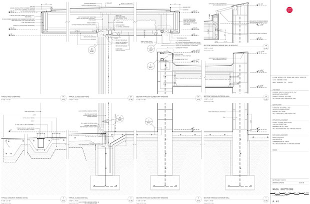
Ground rules for Wall Section sheets.

Layer Set Concept

The model is visible for reference but locked.

Setup

  1. Create wall sections with the section tool, not the detail tool.
  2. [tim: clarify] If the wall section matches a building section, use a hidden section marker layer to create the wall section. Place this marker  in plan directly over the corresponding building section marker at the appropriate wall. The section marker should be on a visible section marker layer if it needs to show in plan.

Drawing References

  1. Use linked detail markers tied to the specific drawing on a Layout.
  2. Source markers may be used to originate a detail but the marker should then be changed to link to a drawing on a layout.

3D

  1. Same as building sections.
  2. Leverage the model as much as possible.
  3. Use the detailing effort to inform the 3D model: unlock the model layers and move 3D elements to keep the model coordinated with the developing details.
  4. Important. Navigate from the view map when starting work in a wall section so the proper layer set locks model elements in the wall section drawing.

2D

  1. Use heavy outlines towards the end of the CD phase once most of the structure and spaces are fully developed.
  2. Lines and fills should be used over the model to convey the necessary amount of detail and scope of work.

download: A 40 WALL SECTION

E, BS, IE

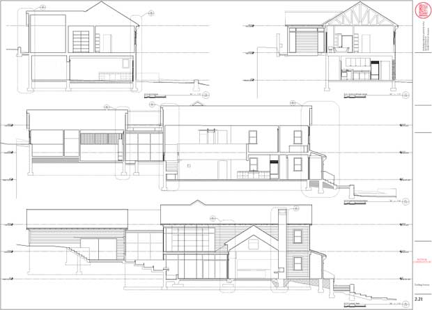
Ground rules for Elevations, Building Sections, and Interior Elevations.

Layer Set Concept

  1. The model is live and unlocked.

Setup

  1. Place section and elevation markers in plan as needed.

Drawing References

  1. Use linked detail markers tied to the specific drawing on a layout.
  2. Do not use source markers for any wall sections as these are developed separately.

3D

  1. Maintain live linked sections to the building model through the life of the project. Remember that appearance of the section is determined both by section attributes of the elements shown, as well as overlay attributes determined by the section tool itself.
  2. Element settings: Utilize element fills cut directly from the model to convey sectional properties.
  3. Section tool settings: Utilize the “uniform pens” settings wherever possible so the overall appearance is consistent.
  4. Profiles are an excellent way to develop an additional level of detail in the building section. They are also handy because they can be updated throughout the life of the project as details develop. Refer to the Profiler Tips and Tricks for some pointers on how to maximize their potential.

2D

  1. Use heavy outlines towards the end of the CD phase once most of the structure and spaces are fully developed.
  2. Add lines and fills as needed to assist with presentation, but utilize the 3D model as much as is sensible.

Floor Plan

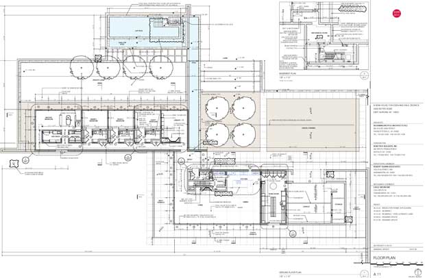
Ground rules for Floor Plans

Layer Set Concept

  1. As many different layer sets as needed to produce drawings.
  2. Different layers and corresponding sets should be used for drawings of a different scale.

3D

  1. If you are drawing an element that will be seen in any other drawing in the set, model it.  This live feedback loop is critical to minimizing mistakes.
  2. Use the graphic control of “model view options”, story display and built-in display functions of library parts to enhance the 2D appearance of the plan as you model the building.
  3. The ArchiCAD library parts are quite good at providing a high level of 2D control.

2D work: Notes, lines, fills, etc…

  1. Exhaust 3D capabilities before you begin to add fills and lines to elements in the model.
  2. Think of 2D work as something static that will live on its own apart from a changing and developing model.
  3. “Model view options” allows a surprisingly high degree of graphic control of the plan view – you may not need to augment at all.
  4. Be sure you have explored all these options before deciding to paint the plans with lots of 2D graphics.  Use composite walls to enhance the amount of detail needed.

download: A 11 FLOOR PLAN