Category Method

CD Sheet Index

From General to Specific – Discipline Prefix to Sheet Number

A surprise. The CSI Uniform Drawing System orders sheets differently than the AIA ConDoc system, following more strictly in the order in which a structure is constructed.

Quoting from the AIA white paper:

Guiding principles include the following:

  1. Segregating information by discipline (both design and construction) to form subsets of the total drawing package
  2. Ordering the subsets to correspond to the natural sequence of construction, closely associating disciplines where topics are similar
  3. Collecting and presenting each drawing (plan, elevation, section) on a sheet dedicated to that drawing type (though different drawing types may be combined for small projects)
  4. Presenting information within each subset from general to specific

Discipline PREFIX

Architects are used to seeing their stuff come first, but ordering the set by the “natural sequence of construction” is rational.

PrefixDiscipline
GGeneral
HHazardous Materials
VSurvey/Mapping
BGeotechnical
WCivil Works
CCivil
LLandscape
SStructural
AArchitectural
IInteriors
EEquipment
FFire Protection
PPlumbing
DProcess
MMechanical
EElectrical
TTelecommunications
RResource
XOther Disciplines
ZContractor/Shop Drawings
OOperations

Sheet TYPE

Within each discipline, sheets are always grouped by type.

PrefaceDescriptionUsage Notes
000Generalproject data
symbols
key notes
general notes
100Plansbuilding plans: minimum 1/4" scale
site plans come under the L series sheets
200Elevationsexterior building elevations
1/4" minimum scale
1/2" for tricky areas
300Sections, Wall Sections1/4" min
1/2" preferred
3/4" for wall sections min
400Scaled-up plans, Sections, or Elevations3/4"
500Details1 1/2" details
3" details
600Schedules and Diagrams
700User-definedtypical detail sheets
800User-definedtypes that do not fall into other categories
9003D representations3D representations
isometrics
photographs

Sheet NUMBERING

Sheets numbers are built from five components:

Discipline – Type – Sequence – Sequence Designator (optional) – Supplemental Designator (optional)

Which in general produces numbers that look something like:

A-102-01-R1

Discipline

Per the CSI table above

Type

Per the Sheet Types in the table above

Sequence

Easy stuff – just a number. The sequence starts with 01 (not 00) and proceeds to 99. Such as:

A-102

Suffix

For sheets added after a numbering sequence has been established, Suffixes can be used. Such as:

A-102-01

Supplemental

Designators indicate revised sheets. “R” indicates a partial revision. “X” indicates a totally revised sheet. Such as:

A-102-X1
Buried Tolerance Toggle

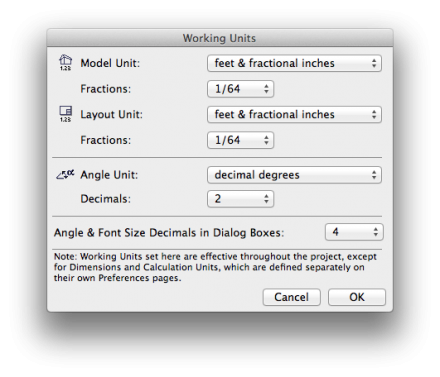
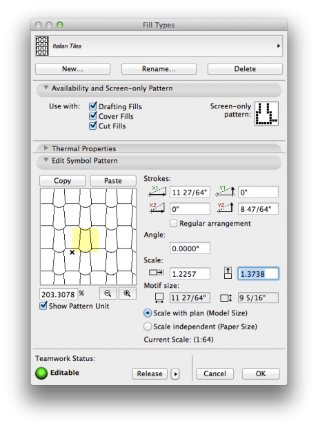
Stymied by lack of significant digits in library part, fill, or curtain wall dialog boxes?

The fix is a Preference: Angle and Font Size Decimals in Dialog Boxes.

fill dialog

working units

0.352777778

A Postscript point is 0.352777778 of a millimeter, or 1/72 of an inch.

Our font size standard is 6-point, sometimes 7-point, type.

Therefore in those “helpful” dialogs asking how large you want your type to be in mm, enter the following:

size in pointssize in millimeters
62.11
72.46

Dimension Essentials

We admit the other dimension post here is completely over-wrought – not that you shouldn’t read it.

Meanwhile here’s a quick and effective how-to:

Teamwork Rollback

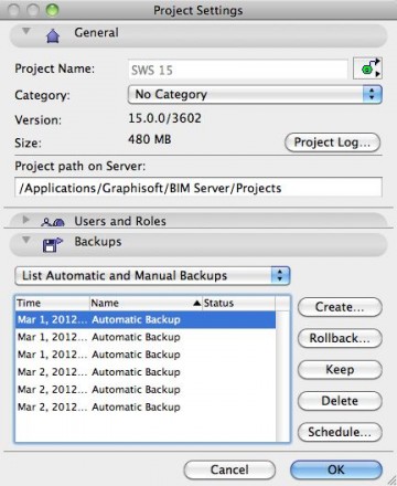
A quick word about rolling back to an earlier version of your work in teamwork.

I just recovered days worth of work, so I’m happy to give this feature a high grade.  Basic description below, followed by an idea of how to use this tool in a more intentional way to manage design options.

Framing Plans: General

Rules for framing plans.

A framing plan shows the following:

  1. The framing for the floor of the current story
  2. The load paths of the current story, in black (load-bearing walls, columns, etc).
  3. Supporting walls below the current story
  4. Partitions of the current story, in gray
  5. Plumbing, mechanical, and electrical fixtures that need to be coordinated with the structure, in gray
  6. Dimensions associated with the framing
  7. Layout lines, grid lines, and work lines (a structural grid if you’re using one, otherwise centerlines and alignments communicating design intent).
  8. Detail cross-references to framing and foundation details, and building sections.

Method

  1. Beams and girders. Model them on layer S-frmg.
  2. Joists and rafters. Represent them on the framing plan with 2-d fill 06 | Framing 16 and related fills, on layer S-frmg-2. If you need other spacings, just make another fill. Repetitive members of a floor or roof can be modeled for other reasons, (3d framing diagrams, sections and details) but we don’t typically use the modeled joists and rafters for the framing plan. Why? Because it is far easier and faster to symbolically indicate repetitive framing than to model it accurately enough for use in a floor plan.
  3. Dimensions: Indicate control points – where to start 16″ o.c. spacings.
  4. Partitions. No fill, separators shown.
  5. Bearing Walls. To show a bearing wall, draw a fill on top of it. This is a non-associated, additional element on layer +S-note.
  6. Annotations.
    1. All annotations should go on the layer +S-note.
    2. If you want an annotation to show in the foundation plan simultaneously, use +S-note-all.
    3. Use a background of pen 91 on text blocks to make them readable when placed on fills.
    4. Structure Notes. General notes such as loads, criteria, etc. are part of the General Notes PDF. Specific notes are added to the plans using text blocks.

Truth or Fiction

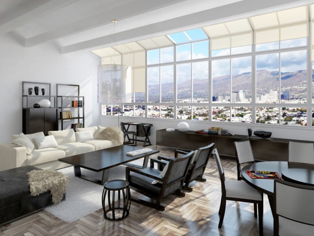
A meditation on the architectural image: photograph? rendering? You decide.

In the nineties I remember the minor kerfuffle involving an image of the interior of the not-yet-open-to-the-public MOMA in San Francisco by Mario Botta, until it was revealed that the image was not the illicit pre-grand-opening photograph captured by a ninja photographer people thought it was, but rather a digital model rendered with great care. I couldn’t find a specific link to verify my memory, but the images of SFMOMA here certainly fit the “is it real?” meme.

There are exceptions, but almost every photorealistic rendering I look at seems to lack a point other than “hey look at me and my shallow command of texture map and lighting effect.” The technology amazes, but let’s remember why Avatar was not such a good movie, and why Pixar seems incapable of making a bad one, and what architecture is for, and the reason we’ve decided to spend our lifetimes making buildings. Stealing the conceit from the Avatar link above: a CGI image is distracting like incredibly good-looking people are (the stereotypical fashion model) until you realize how vapid and self-centered and boring it is. And like incredibly good-looking people who mange to also be interesting, smart, and compassionate – CGI that *does* jump the gap between documentation and art has an uphill fight to prove its worth.

These are the same issues photography faces as an art form.

There’s a point to be made here that I’ll cite with reference to Robert Bringhurst, the typographer, poet and writer: this visual material is at its best when it self-effacingly serves the (architectural) content.

Referencing what the poet said: a rendering should be window, opening a view through to something vital.

So what’s that point again? I don’t know… perhaps it is to say that just because one can, does not mean one should. Or better: if you can, don’t forget to ask yourself why and to what effect?

Vermeer is still the gold standard.

Lighting Design

Le Corbusier said:

“Architecture is the masterly, correct and magnificent play of masses brought together in light.”

One might infer from this famous utterance that with the absence of light architecture is not possible.

Pens update

The pen set concept is a powerful one. Let’s talk about how to use pens, and pen sets, effectively.

Trim


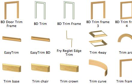
Who knew? We have many options for quickly and effectively modeling trim in traditional and contemporary structures. One of the last steps in reaching a true “no drafting” state of bliss regarding elevations, both exterior and interior.