A nice summary of the issues with links to new methods of addressing the question of horizontal furring strips in exterior rain-screen assemblies. The answer to the efficacy of horizontal battens depends on the porosity of the siding material.

A nice summary of the issues with links to new methods of addressing the question of horizontal furring strips in exterior rain-screen assemblies. The answer to the efficacy of horizontal battens depends on the porosity of the siding material.
Sometimes referred to as housewrap, or a WRB.
GBA article number one tells us all about them. GBA article number two fills in the details of the liquid-applied version.
After reading both, the liquid product seems better – a little more expensive, but a much better seal.
The least expensive way to provide electric power to a structure is through a PV array. A photovoltaic system is clean, reliable, local, simple, frugal, and even beautiful, if you can afford the steep first cost and have a site or roof that has good access to the sky. The grid as your battery on sunny days is still the best bet in net-metered Virginia, as opposed to being fully off-grid. We’re waiting for battery technology to catch up. AltEnergy is our favorite local vendor.
Green Building Advisor has the details.
Highlights today:
Nothing original here: the air sealing checklist from the 2009 IRC. Use it well. This is why a good 3/4″ = 1′ building section drawing can be so useful: a thoughtful section drawing will show the air barrier; you should be able to trace the air barrier “balloon” all the way around the building without lifting your pencil off the sheet.
The specific code requirements are:
N1102.4.1 Building thermal envelope. The building thermal envelope shall be durably sealed to limit infiltration. The sealing methods between dissimilar materials shall allow for differential expansion and contraction. The following shall be caulked, gasketed, weatherstripped or otherwise sealed with an air barrier material, suitable film or solid material.
And the checklist:
| COMPONENT | CRITERIA |
|---|---|
| Air barrier and thermal barrier | Exterior thermal envelope insulation for framed walls is installed in substantial contact and continuous alignment with building envelope air barrier. |
| Breaks or joints in the air barrier are filled or repaired. | |
| Air-permeable insulation is not used as a sealing material. | |
| Ceiling/attic | Air barrier in any dropped ceiling/soffit is substantially aligned with insulation and any gaps are sealed |
| Attic access (except unvented attic), knee wall door, or drop down stair is sealed. | |
| Walls | Corners and headers are insulated. |
| Junction of foundation and sill plate is sealed. | |
| Windows and doors | Space between window/door jambs and framing is sealed. |
| Rim joists | Rim joists are insulated and include an air barrier. |
| Floors (including above garage and cantilevered floors) | Insulation is installed to maintain permanent contact with underside of subfloor decking. |
| Air barrier is installed at any exposed edge of floor. | |
| Crawlspace walls | Insulation is permanently attached to walls. |
| Exposed earth in unvented crawlspaces is covered with Class I vapor retarder with overlapping joints taped. | |
| Shafts, penetrations | Duct shafts, utility penetrations, knee walls and flue shafts opening to exterior or unconditioned space are sealed. |
| Narrow cavities | Batts in narrow cavities are cut to fit, or narrow cavities are filled by sprayed/blown insulation. |
| Garage separation | Air sealing is provided between the garage and conditioned spaces. |
| Recessed lighting | Recessed light fixtures are airtight, IC rated and sealed to drywall. |
| Exception-fixtures in conditioned space. | |
| Plumbing and wiring | Insulation is placed between outside and pipes. Batt insulation is cut to fit around wiring and plumbing, or sprayed/blown insulation extends behind piping and wiring. |
| Shower/tub on exterior wall | Showers and tubs on exterior walls have insulation and an air barrier separating them from the exterior wall. |
| Electrical/phone box on exterior wall | Air barrier extends behind boxes or air sealed type boxes are installed. |
| Common wall | Air barrier is installed in common wall between dwelling units. |
| HVAC register boots | HVAC register boots that penetrate building envelope are sealed to subfloor or drywall. |
| Fireplace | Fireplace walls include an air barrier. |
Listening to their iPods in apartments that don’t exist yet, walking their dogs down prospective city streets, playing chess together in a forthcoming park near Potrero Hill.
Who are these little humans and what are they doing in our images? The New York Times and BLGBLOG looked into the question of human figures in architect’s renderings. We’re asking ourselves the same question
George Hershey’s The Lost Meaning Of Classical Architecture paints classical architectural motifs a color grounded in unpleasant realities: Sacrifice. Blood. Enslavement. After reading that book I never thought of the Caryatids the same way again, neither the little Dwarfs holding up the front of Michael Eisner’s office; both appear reasonably content holding the building up, but if you accept George Hershey’s line of argument, they are slaves pressed into service. Michael Graves should have known better.
Technology has changed, but it seems we may have come full circle.
The ancients with incredible skill chiseled the image and likeness of humans from a block of stone and deployed the resulting figure into the service of their building.
And today it is a bit the same except we capture them from the digital ocean. It’s nice when Anderson Cooper or Angelia Jolie or underprivileged families will hang around well… forever and legitimize and tart up ones sales pitch for a project, and hopefully the pitch places it above critique, as the project is apparently already an essential part of the city.
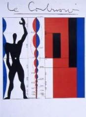
 I think there was a post-classical, pre-digital phase when human figures transcended a particular time and place and stood for all humans in all places, since they didn’t sport recognizable backpacks or fashion accessories or haircuts. All are descendants of da Vinci’s Vitruvian Man, and I’m thinking of Le Corbusier’s modulor figure, or WG Clark’s beautiful ink drawings for Robert Venturi, and other mid-to-late century examples of where, in Corb’s case anyway, the figure was anonymous and functioned as a humanistic ruler to make a point about the building’s proportion or scale. These days we release our scalies into virtual architectural terrariums and hope they will be happy there.
I can’t really add much to the coverage cited above, and I encourage you to have a look at the NYT piece.
In a lighter vein (or maybe not) there’s this:

Don’t confuse lighting design for still images or stage with lighting design for an architectural project. Related? Yes. Both important? Yes. Different? Yes.
Dwight Atkinson, a good architectural educator and writer about ArchiCAD-Artlantis workflows, says flat out that the only effective workflow in Artlantis is to think like a Director of Photography and light your scene accordingly. The basic technique is called three-point lighting, the three points, or lights, being
So by way of a practical example see the lighting professional’s tutorial below. Videography is not our trade. Yet we share the videographer’s design sensibilities, and understand what it means to fret about foreground, background, contrast, highlighting, balance, presentation, and nuance, always, of course, with a goal of presenting subject material (in this case, a speaking person on film) as effectively as possible.
The lighting technical director at Pixar has written a book. I’m sure we should read it. But until we get around to that, an equally effective learning experience might be some quality time meditating on the image at the head of this post, painted between bar fights by Caravaggio in 1594. He was 23 years old.
It would be incorrect to say Caravaggio invented these principles of lighting, but he was certainly one of the first artists to effectively capture them, in hardcopy rising to the level of Art.
I offer the moonlight grazing the wing of the angel cradling St. Francis, and rest my case.
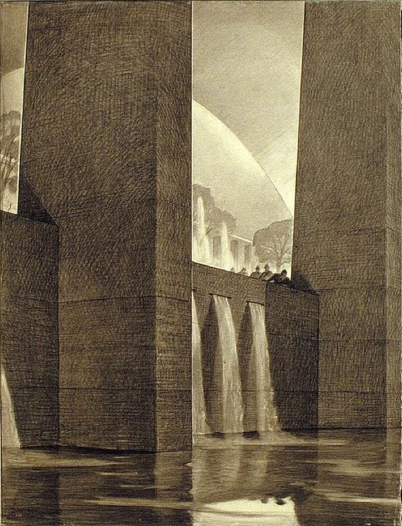
Closer to home, Hugh Ferriss‘s work also evidences a deep appreciation of foreground and background. I’m convinced he learned a thing or two from Caravaggio. Pugilistic affinities aside, you couldn’t ask for a better teacher.


Footcandle? Lumen? Illuminance vs luminance? Zonal Cavity Method?
Lightsearch.com has a page with a nice summary of lighting and illumination formulas.
A multi-dimensional database of atmospheric carbon, tracked by season and location across time. It will be helpful to unpack the contents a bit before viewing:
Fascinating. Full-screen it for clarity in the details.
Teaser: there is a remarkable moment at the two-minute mark.
Climate scientists believe 350 PPM is the line above which runaway climate change is inevitable. We passed the 350 PPM mark in 1989.
What does it mean, this spectacular rise in global CO2? There are thousands of examples pointing toward a meaning, I am sure. Here is one: in the last century the temperature in western North America increased less than 2 degrees F, but as a result, beginning mostly in the last decade, the great native lodgepole pine forests in western North America are dying at an extraordinary rate. Eighty percent of British Columbia’s mature lodgepole pine trees will be lost before 2013. In Colorado over 80,000 square miles of mature lodgepole pine forest have been lost. All this with less than 2 degrees of warming. Before the predicted 3 to 8 degrees of warming by the end of this century.
The temperature is not killing the trees directly – a beetle is, now that winters are warm enough not to keep the beetles in check. What happens to the other creatures populating a complex forest ecosystem when the trees are gone? What happens when a carbon-negative forest dies and becomes a carbon-positive emitter as is currently happening in western North America?
Buildings consume half of all energy produced in the United States. And therefore, at least indirectly, architects are complicit participants in the transfer of ancient carbon out of the earth and into the atmosphere. By the same token, this puts architects in a powerful position to do something about the problem. How should day-to-day practitioners of Architecture respond?
While we ponder that, time is wasting. 2010 marked the largest increase in atmospheric carbon in history – about 6% – a staggering jump by any measure, and rendering every national and international mitigation goal moot – because none of them remain within reach. Bill McKibben says we’re living on a different planet now… he may be right.
For more about the earth’s carbon cycle jump to the informative NOAA Earth System Research Laboratory CarbonTracker pages.

A roofer’s perspective: the Ten Rules of Roof Design from GBA.com.
The most amusing part of the post at GBA.com is the author’s “preemptive comment directed at indignant designers.”