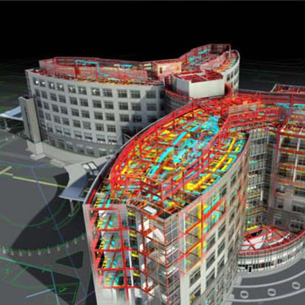
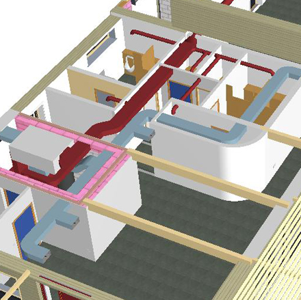
It’s a complex world.
Maps simplify the world such that we can cling to a diagram and make sense of the complexity. Whoa. Exactly what a Feynman diagram is. Lets set aside questions of philosophy and design and what makes the world clock tick, and just say that organizing, and building a structure is not easy in the real world, and neither is it easy in the virtual world. To help us get a grip on all the pieces and parts, we establish classes of elements, and sort by class. Thus it is with layers, and layer combinations.
Let’s describe the classes of layers in use by our office. Nothing unusual, really. We deploy the following sets of layers targeted to different design activities. (These are not classes of layers, strictly speaking, but classes of groups of layers – which take on a life of their own.)
3d design work
Where we spend most of our time – at least in the beginning. All building parts, very little annotation. This category includes subsets of the structure for analysis and design (framing, sitework, or for example)
printing
During the design phase: just the layers needed for simple and effective design-phase communication.
For condocs: everything just so… annotations, gridlines, worklines, notes, and so forth.
presentations, live
All building and site, none of the annotation: for client meetings and design updates.
export
To our internal rendering software, or to engineers…
sitework
Because we spend a lot of time grappling with site meshes, imported data from surveyors, aerial photographs.
annotation and documentation
For the detailed graphic design that is a technical floor plan or section: notes, dimensions, grid and work-lines.
Organizing Lists
ArchiCAD offers so much granular control over the details that this “list within a list” concept applies across the board. So our layer combination list is organized by prefix according to the needs listed above. The prefixes are mandatory, the descriptors following can be customized.
Remember that the names of layer combinations strictly adhere to views, so you can’t change the name of a layer combination without breaking the view. The view will maintain its characteristics, but won’t be able to find the layer combo that defines it any longer. Changing layer names is more forgiving.
Navigation
It is always more efficient and effective to organize your work by named layer combination. Avoid picking through a haystack of layers and switching on/off to get the view you need. Do it once, name it and save it if it’s important to you.
| Preface and Name | Usage Notes |
|---|---|
| 3d | framing | for designing working model - framing |
| 3d | framing no site | for designing working model - structure no site |
| 3d | model | any other subset view |
| 3d | model | for designing |
| 3d | model no lights | for designing |
| 3d | present 3d | the whole model for export or presentation (BIMx, Artlantis) |
| 3d | site work | for designing working model - site |
| condoc | A demo | demo plan |
| condoc | A electric | electric, lighting, power plan |
| condoc | A furniture | furniture plan |
| condoc | A plan 1/2 | 1/2" scale detail plans need their own annotation layer |
| condoc | A plan 1/4 | contract document fully annotated and dimensioned |
| condoc | A plan 1/10 | small scale plan fewer layers, simpler model view, small-scale pen set |
| condoc | A plan finish | floor finish plan |
| condoc | A rcp | |
| condoc | ESD | all ESD views are generated from this single combo. exceptions: interior elevations, wall sections |
| condoc | IE | interior elevations |
| condoc | L plan | site plan |
| condoc | L plat plan | plat location plan |
| condoc | M plan | mech plan |
| condoc | P plan | plumbing plan |
| condoc | S fndn | foundation plan separate combo because??? |
| condoc | S plan | structure plan |
| condoc | WS | wall sections |
| dd | A existing | existing conditions |
| dd | A plan | floor+roof plan - working same as above, but includes hidden ESD markers, gridlines, layout lines, annotations, and so forth. create "working" versions of each combination as required. |
| dd | A plan existing | aexisting conditions plan dd addn'l combos as required to include existing elevations (E) and sections (S) |
| dd | area | area diagram |
| dd | plan detailed | simple annotations and dimensions colored zones furnishings as required |
| dd | plan simple | no dimensions no fills just walls |
| export | DWG | simple, clean, minimum fills |
| site | aerial | aerial bitmaps at scale |
| site | cut-fill | mesh calculations |
| site | mesh working | mesh construction |
| site | survey | survey import |
| x | import a, b, c... | other scans or sketches for printing at scale use alpha indexing for subsequent layers |
| x | sketch a, b, c... | sketch plans for printing at scale use alpha indexing for subsequent layers |
| z | all | all layers on, unlocked |
| z | meta | access to the bd-MAP layers for office standards |
| z | object lab | object creation, drafting, safekeeping |

